Namaste!

Welcome to a blog about things in my life, observations about the world, and just silly stuff. Enjoy!

Monday, April 29, 2013

Accelerometers, Gyroscopes, and Filters Oh My!

Accelerometer + Gyroscope = Cheap (grad school budget) IMU
A gyroscope is a device that measures orientation using principles of angular momentum.  Wikipedia has a great description of gyroscopes (http://en.wikipedia.org/wiki/Gyroscope), so if you want to read more I'd follow that link.  Unfortunately, gyroscopes tend to drift over time which means for longer periods of time the measurement becomes inaccurate.  Enter the accelerometer, which is used to correct for this drift.

An accelerometer is a device that measures (proper) acceleration.  Again, if you want to know more about these devices check out Wikipedia's well written page on these devices (http://en.wikipedia.org/wiki/Accelerometer).  Accelerometers do not have drift but are unstable for shorter time spans.  Therefore Inerial Measurement Units were created and take advantage of the benefits of an accelerometer and gyroscope.  The accelerometer provides a reference to the gyroscope and is used to remove the drift of the gyros.  With the drift removed, this sensor combination offers more accurate long term motion detection and therefore can be used as a position tracking sensor for an object.  A filter (e.g. Kalman) is usually implemented with an IMU and is the last component of my make-shift IMUs. 


Accelerometers
As a refresher, here's the accelerometer from Adafruit Industries that I'll be using to sense motion of the pendulums linkages (https://www.adafruit.com/products/1231)
ADXL345 - Triple-Axis Accelerometer (+-2g/4g/8g/16g) w/ I2C/SPI - Click Image to Close
ADXL345 Triple Axis Accelerometer


I soldered each of the accelerometers (see Adafruit link above for soldering and connection tutorial) and connected them to the Arduino Mega 2560.  Below are the pin connections for these two components.
Accel          Arduino
VIN    <—>   3.3V    
GND   <—>   GND
SDA    <—>   SDA 20
SCL    <—>   SCL 21


Accelerometer to Arduino
The accelerometer could also be connected to the 5V output pin of the Arduino, since the accelerometer regulates the voltage to 3.3V. 

Next I plugged the Arduino into my MacBook Pro, started the Arduino software, and selected the correct board (Tools >> Board >> Arduino Mega) from the pull down menu.  I copied the sensor test sketch (provided by Adafruit) into my Arduino library folder and opened the file sensortest.pde.

The sketch to test the accelerometer is designed to output the sensor's data into the serial monitor.  After compiling the sketch, I clicked on the magnifying glass icon on the top right of the sketch to open the serial monitor.  This allows you to see the sensor's output while moving it (real time) and test each of the accelerometers.  This accelerometer measures acceleration (g's) in three dimensions and here is the output to the serial monitor:

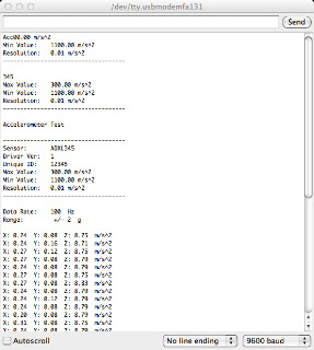
Serial Monitor for Accelerometer Output


Gyroscopes
As a refresher, here's the gyroscope from Adafruit Industries that I'll be using to sense motion of the pendulums linkages (https://www.adafruit.com/products/1032)

L3GD20 (L3G4200 Upgrade) Triple-Axis Gyro Breakout Board - Click Image to Close
L3GD20 Triple Axis Gyroscope

I soldered each of the gyroscopes (see Adafruit link above for soldering and connection tutorial) and connected them to the Arduino Mega 2560.  Below are the pin connections for these two components when connecting the gyroscope for SPI (Serial Peripheral Interface) communication.
Gyro          Arduino
VIN    <—>   5V    
GND   <—>   GND
CS   <—>   Digital 4
SAO    <—>   Digital 5
SDA    <—>   Digital 6
SCL    <—>   Digital 7


Alternatively, since the L3FD20 supports both SPI and I2C (Inter Integrated Circuit) communication, you can connect the gyroscope so it uses I2C communication (fewer wires).  Also of minor note: I2C is pronounced "I squared C".
Gyro          Arduino
VIN    <—>   5V    
GND   <—>   GND
SDA    <—>   SDA 20
SCL    <—>   SCL 21

In case you haven't already, make sure to select the correct board (Tools >> Board >> Arduino Mega) from the pull down menu when communicating between your computer and the Arduino.  I copied the Adafruit_L3DG20 Gyro Code sketch (provided by Adafruit) into my Arduino library folder.  I had to make a few modifications (missing libraries) to the sketch provided by Adafruit before it would run and I also added some comments to the code... but all credit for this sketch should go to AdaFruit Industries.


//Adafruit_L3DG20 Gyro Code

// Import Libraries
#include
#include
#include

// Must first call a constructor to create a device object.
// There are two forms of the constructor:
// 1. I2C wiring
// Adafruit_L3GD20 gryo();  no need to specify pins for I2C
//
// 2. SPI Wiring
// Adafruit_L3GD20 gyro(int8_t cs, int8_t mosi, int8_t miso, int8_t clk);

// Define the pins for SPI wiring
#define GYRO_CS 4 // labeled CS
#define GYRO_DO 5 // labeled SA0
#define GYRO_DI 6  // labeled SDA
#define GYRO_CLK 7 // labeled SCL

Adafruit_L3GD20 gyro(GYRO_CS, GYRO_DO, GYRO_DI, GYRO_CLK);

// ----- INITIALIZATION ----- //
// Initialize the gyro with the sensitivity range that will be using
//bool begin(l3dg20Range_t L3DS20_RANGE_250DPS);
// where the second variable above (range) can be one of
//L3DS20_RANGE_250DPS //- for 250 degrees-per-second range (default)
//L3DS20_RANGE_500DPS// - for 500 degrees-per-second range
//L3DS20_RANGE_2000DPS// - for 2000 degrees-per-second range

//int incomingByte = 0; // for incoming serial data

void setup()
{
  // Open serial port and sets data rate to 9600 bps
  Serial.begin(9600);
 
  // Try to initialise and warn if we couldn't detect the chip
  if (!gyro.begin(gyro.L3DS20_RANGE_250DPS))
  {
    Serial.println("Oops ... unable to initialize the L3GD20. Check your wiring!");
    while (1);
  }
}


// ----- SENSING ROTATION ----- //
// To sense rotation must first call the 'read()' function to take a reading
// void read(void);
// This function takes no parameters.  After calling 'read()'.  The raw x,y,z
// readings can be retrieved from the device object's 'data' member.
// data.x - x-axis rotation rate in degrees-per-second
// data.y - y-axis rotation rate in degrees-per-second
// data.z - z-axis rotation rate in degrees-per-second

void loop()
{
  // Read the input
  gyro.read();
  // Print out what was read in
  Serial.print("X: ");
  Serial.print((int)gyro.data.x);  
  Serial.print(" ");
  Serial.print("Y: ");
  Serial.print((int)gyro.data.y);  
  Serial.print(" ");
  Serial.print("Z: ");
  Serial.println((int)gyro.data.z);
  Serial.print(" ");
  // Delay 100 milliseconds before the next reading
  delay(100);
}

// ----- ALTERNATE UNITS ----- //
// The values reported by the read() function are in degrees-per-second (dps).
// For some calculations, it may be more convenient to work in radians. 
// To convert dps to radians-per-second (rad/s), simply multiply by 0.017453293 as
// in the following code:
//#define SENSORS_DPS_TO_RADS (0.017453293F)  /**< Degrees/s to rad/s multiplier */
//
//void loop()
//{
//  gyro.read();
//  Serial.print("X: "); Serial.print((int)gyro.data.x * SENSORS_DPS_TO_RADS);   Serial.print(" ");
//  Serial.print("Y: "); Serial.print((int)gyro.data.y * SENSORS_DPS_TO_RADS);   Serial.print(" ");
//  Serial.print("Z: "); Serial.println((int)gyro.data.z * SENSORS_DPS_TO_RADS); Serial.print(" ");
//  delay(100);
//}

Just like the sketch to test the accelerometer, the gyroscope's sketch is designed to output the sensor's data into the serial monitor for real time viewing.  After compiling the sketch, I clicked on the magnifying glass icon on the top right of the sketch to open the serial monitor.  This allows you to see the sensor's output while moving it and test each of the sensors.  This gyro measures degrees per second (deg/sec) in three dimensions, so if you want to convert to units of radians/sec see the above code section "Alternative Units".
Here's the output from the gyroscope when viewed in the serial monitor.
Serial Monitor for Gyroscope Output


To SPI or I2C?  That is the question.
SPI was invented by Motorola and I2C was invented by Phillips as a means of serial communication.  Instead of me pretending to be an expert on I2C, I found this great posting from this other blog about I2C (http://dev.emcelettronica.com/i2c-or-spi-serial-communication-which-one-to-go)...

SPI supports full duplex communication with higher throughput than I2C. It is not limited to 8-bit words so you can send any message sizes with arbitrary content and purpose. The SPI interface does not require pull-up resistors, which translates to lower power consumption. However, I2C is simpler by having fewer lines which means fewer pins are required to interface to an IC. When communicating with more than one slave, I2C has the advantage of in-band addressing as opposed to have a chip select line for each slave. I2C also supports slave acknowledgment which means that you can be absolutely sure that you’re actually communicating with something. With SPI, a master can be sending data to nothing at all and have no way to know that. In general SPI is better suited for applications that deal with longer data streams and not just words like address locations. Mostly longer data streams exist in applications where you’re working with a digital signal processor or analog-to digital converter. For example, SPI would be perfect for playing back some audio stored in an eeprom and played through a digital to analog converter DAC. Moreover, since SPI can support significantly higher data rates comparing to I2C, mostly due to its duplex capability, it is far more suited for higher speed applications reaching tens of megahertz. And since there is no device addressing involved in SPI the protocol is a lot harder to use in multiple slave systems. This means when dealing with more than one node, generally I2C is the way to go.

Kalman Filter
The Kalman filter uses the measurements from the IMU sensors, which like any real-world measurement contain noise, to produce an estimates of unknown variables (e.g. angular position) that tend to be more precise than those based on a measurement from only an accelerometer or gyroscope. 

Matlab calling Arduino... are you there?

Matlab: "Hello, Arduino?"
Arduino: "Hello Matlab!"

This post gives an example of how to communicate between Matlab and the Arduino via a USB port (e.g. serial communication).  The accelerometers were purchased from Adafruit Inustries (discussed in another post) and connected to an Arduino Mega 2560.

Setup:
1. Connect the Arduino to your computer with the USB cable.
2. Make sure the sensor (i.e. accelerometer) is connected to the Arduino.
3. Open, compile, and upload the accelerometer sketch (discussed in a previous post).  The TX LED on the Arduino should blink every time it transmits data.
4. Open Matlab and create a new m file with the following code.  Alternatively, you could also copy and paste this into the command window and run the script there.

close all; clear all; clc
% create a serial port object called 's1' with a baud rate of 9600 (same as Arduino's sketch)
s1 = serial('/dev/tty.usbmodemfa131', 'BaudRate', 9600)
fopen(s1);
fprintf(s1, '*IND?')
ind = fscanf(s1)
% Read and display the data the Arduino is transmitting continuously in the command window
s1.TimerFcn=@(x,y)disp(char(fscanf(s1)))
% Close serial port when you want to stop displaying data in Matlab's command window
fclose(s1)

More to come...

Potato Racing!


POTATO RACING
What is potato racing?  Well its something the Children's Hospital Colorado does every year around Saint Patrick's Day for the kids... and adults.  Basically, you get an official racing potato and a pine car racing wheels set and try to build the fastest, coolest, cleverest potato.  There is a beauty contest and a racing contest.  Last year our department entered the three potatoes: the couch from the Simpson's, Sonic the Hedgehog, and a Minion.

2012 Entries


Potato Couch with Homer, Marge, Lisa, and Bart Simpson

Unfortunately, the couch and Sonic ended up racing each other in the first heat.  We did end up getting 2nd in the beauty contest though!


As the department in the hospital with the most engineers, I feel like we should be sweeping the competition by using our design/build super powers.  Time for some over-engineering!

This year since I have access to a laser cutter and machine shop, I decided to make some chassis for our potatoes out of acrylic with carbon fiber tubing for the wheel axles.  Here's a final version of a chassis... not the original design but do to some manufacturing issues this is the first iteration.


For my potato this year I was inspired by the EL wire I found on several electronic parts websites and the movie Tron (since the movie used Vicon motion capture systems, similar to our Vicon MoCap system).  So I decided to make a potato like the motorcycles in the movie.

To start, I traced out all the places I'll be cutting away and carving out.
Outline for chassis
EL Wire outlines and Power Inverter
I purchased some EL wire and an inverter from AdaFruit Industries... once again they have the coolest stuff.       https://www.adafruit.com/products/676

I used a Drumel to carve out the grooves for the EL wire, chassis, and inverter.
EL wire grooves
Next, I painted the potato with black spray paint and drilled holes through the potato for the wheel axles (one of the rules is the axles must pass through potato).  I plugged in 2 AA batteries to the inverter and assembled everything.

I give you... drum roll... Tater Tron and the other 2013 team CGMA entries!

2013 team CGMA entries (Tater Tron, Hungry Caterpiller, Darth Tater, Angry Spuds)

We experimented with our own chassis this year.  Here's the acrylic chassis with carbon tubing for the wheel axles. 
Acrylic chassis, laser cut to precision.

Complete acrylic/carbon fiber chassis


In the spirit of St. Patrick's day, I'd like to say Go n-éirí an bóthar leat (guh n'ayr'ee uhn boehuhr l'aet): "May the road succeed with you!" to all of Tater Tron's competitors.  I think you're going to need it this year :)


Driving Stepper Motors

This post discusses the integration of a quad stepper motor controller and 3 stepper motors, which are controlled by an Arduino Mega 2560.

Stepper Motors
The stepper motors I purchased have four wires (red, yellow, green, blue) used to control the motor.  In order to confirm the color combinations provided in the motor's drawing and thus find the wire pair that controls each coil, I used a multimeter to measure the amount of resistance between each motor pairing.  The wires with less than 10 Ohms of resistance belong to the same coil.  Before wiring your motor to a controller, I'd suggest double checking the wiring for any stepper motor using this method.  For this particular motor and driver board the wiring is (from left to right): red, green, yellow, blue.

Quad Stepper Motor Controller
I selected this particular stepper motor because it can control up to 4 stepper motors simultaneously and interfaces with an Arduino (Mega).

Quadstepper Motor Controller
I used 3 (pelvis, hip, knee joints) stepper motors for the compound pendulum.  In order to power the controller and motors, I had to determine how much power the controller needs for all the motors.  Since this robot won't be mobile, I wanted to have a wall outlet supply power to the motors and controller (instead of batteries).  These particular stepper motors are rated at 12V and 0.33A.  The controller has an operating voltage range of 8-35V and a max current of 2A.  The total current needed by the controller for the board is I = 3*0.33A ~ 1A.  To be safe and have the option to give the motors a little extra current if needed, I ended buying a wall adapter that has a 2.1mm barrel connector and can supply 12V and 2A to the controller.  Also by using a wall adapter that can supply 2A, I won't need to purchase a new adapter if I add a fourth motor (ankle joint) to the system.

Arduino Interface
The Arduino Mega connects to the driver board using 6 wires per motor (Enable, MS1, MS2, MS3, Direction, and Step).  Sparkfun has an Arduino library and initial code for using the Quadstepper motor controller with and Arduino.  The code for the quad-stepper driver requires the following pin connections:

Motor1 STP pin: mega pin 11
Motor2 STP pin: meag pin 5
Motor3 STP pin: meag pin 6
Motor4 STP pin: mega pin 46

And then you can set the remaining pin assignments for the direction, enable, and MS1-3 wires to whatever pins you want on your Arduino.

After confirming the connections and code for one motor, I added the other two motors and modified the code accordingly.  Here's a video of testing one stepper motor.


Sunday, February 24, 2013

Robotic Compound Pendulum

Project Description
As part of my graduate course and overall learning experience, I decided to build a robotic compound pendulum.  There are numerous projects and videos available on the web for inverted pendula, self balancing pendula, etc. but I have not come across any robotic compound pendula.  The motion of a compound pendulum has been likened to the motion of your leg while swinging when you walk (a.k.a. swing phase of gait).  For an introduction to gait and the gait cycle, check out my Lego video: https://www.youtube.com/watch?v=-opbwBSOonw

Since my dissertation is examining the swing period of gait, I thought it would be cool to build a robotic compound pendulum that could mimic various gait patterns, be tested in our motion capture lab, and compared with actual human gait data and the theoretical Matlab model I am writing.  The initial gait patterns I'd like to mimic are normal, lower limb amputee (above knee), and stiff knee gaits.

Here are some SolidWorks model views of the robotic compound pendulum; where the red linkage simulates transverse pelvic motion, the blue linkage simulates sagittal thigh motion, and the green linkage simulates sagittal shank motion.


The following series of posts will provide instructions and explanations of how I built a robotic compound pendulum.  There were several goals for this project:
   1. Create a pendulum that mimics various clinically seen gait patterns.
   2. Create a pendulum that can be used as a teaching tool for dynamics, gait, and robotics.
   3. Share my experience with others and offer instructions on how to build such a robot.
   4. And lastly, make a robot that meets the requirements of my graduate robotics class 'grad project'.

Below is a list of the parts I have purchased for the robot and links to various websites and resources.  Each component or system will be described in more detail in future posts.

Processor
I decided to use an Arduino Mega 2560 as the processor for the robot.  As a bonus it is supposed to interface easily with Matlab (http://www.mathworks.com/academia/arduino-software/).  The programming environment for Arduino sketches (a.k.a. functions, programs) are compatible with a Mac and the software development kit is free (http://arduino.cc/en/main/software).

Arduino Mega 2560
Motors
I decided to use three (pelvis, hip joint, knee joint) stepper motors to actuate the linkages because the position and torque production of each motor is important for this project. I purchased three (ankle can be added at a future time) stepper motors from SparkFun (https://www.sparkfun.com/products/9238).
Stepper Motor (200rpm)
Also, I purchased the motor controller from SparkFun (https://www.sparkfun.com/products/10507) because it can drive up to four stepper motors at a time.  Eventually, I'd like to add a motor for the ankle joint.  So when I do add this fourth motor, I won't have to buy another motor controller but simply have to solder the motor and Arduino connections.
Quad-Stepper Motor Controller

Sensors
As a proof of concept for future projects, I decided to sense the position of robot's linkages with accelerometers and gyroscopes.  Unfortunately, purchasing 3 inertial measurement units (IMU) was not in my budget for this project but I should be able to achieve similar results with accelerometers, gyroscopes, and a Kalman filter... since those are the components of an IMU!  I purchased three accelerometers and 3 gyroscopes from Adafruit Industries (https://www.adafruit.com/); which has outstanding tutorials and cool projects for all levels.  Sparkfun also has various accelerometers, gyros, and IMUs that would work equally as well.  The pages for each of the sensors from Adafruit has soldering, connections to the Arduino, and Arduino sketches and libraries for each sensor so you can get up and running quickly.

Here's the accelerometer (https://www.adafruit.com/products/1231)
ADXL345 - Triple-Axis Accelerometer (+-2g/4g/8g/16g) w/ I2C/SPI - Click Image to Close
ADXL345 Triple Axis Accelerometer
And here's the gyroscope (https://www.adafruit.com/products/1032)
L3GD20 (L3G4200 Upgrade) Triple-Axis Gyro Breakout Board - Click Image to Close
L3GD20 Triple Axis Gyroscope
I'll add posts to explain the software and hardware as I integrate these components together.
 

Mmmm.... humus!

I do love chickpeas, but this post is not about yummy hummus... instead it is about "humus" also known as black gold or compost.  After a considerable amount of research on the types of containers, ways to compost, the ins/outs of compost, and types of composting (i.e. vermicompost - with worms) I finally selected a bin and have started my pile of rot!  I thought I'd share my rotting adventures, what works, what doesn't work, etc.

Living Colorado ruled out vermicomposting for me, since they have a narrow temperature range (40-70deg) and according to many sites require garage storage in the cooler months... that is if you don't want to buy new ones each year.  Too much work and I don't feel like sharing my pain cave with worms.  I also considered a tumbler vs a bin... and after reading the pros/cons of each felt that a bin was ideal for my busy schedule.  I only have to turn or aerate the bin occasionally compared to a tumbler.  Also after speaking with several friends who have piles, those with bins seem to have greater success than those with tumblers.  So bin it is.


Getting Started
After assembling the bin (very easy), I lined it with about 2 inches of a high carbon material (i.e. straw, twigs, leaves, hay, peat)... I chose peat because I had a gargantuan bag of it already.   I also noticed that most readily available straw is wheat and since I have celiac disease decided not to risk exposure (no matter how minimal it might be).  I couldn't find any info about whether or not gluten gets broken down in the composting process... I'd be interested if anyone knows (that is assuming anyone reads this blog!).  Then I added about 2 more inches of organic mushroom compost on top of the peat.  Next I put my kitchen scraps in (currently being stored in an old protein powder container) and covered them with the mushroom compost.  We'll see how it goes.

After School Special
Here are some tips for composting that I compiled during my research.  Compost consists of four main elements (or compounds):

      Carbon (C): is the energy source for microbes that decomposes the items in the pile
             - materials high in carbon are referred to as "brown" materials
             - C materials help dry out your pile if its too wet/moist
             - C materials also reduce odors
             - microbial oxidation of C produces heat, which aids in the process

     Nitrogen (N): provides the microbes their dietary protein
             - materials high in N are referred to as "green" materials
             - N materials help add moisture to your pile if its too dry

      Oxygen (O): aids in the decomposition process and is required for oxidation of C
             - turning or aerating your pile helps keep the decomp process aerobic

      Water (H2O): pretty self explanatory... everything organic needs water


If you read about an item's C:N number, this is the ratio of Carbon to Nitrogen content in that item.  For example, pine needles have a C:N of about 60-110 which means that there are ~60-110 parts of Carbon to every one part of Nitrogen.  Vegetable matter has a C:N of ~15-25, so you guessed it... there is a higher Nitrogen content in veggies than pine needles.

Here is a brief list of the items that are acceptable to put in your compost bin (mostly, limited to what I will be adding).

   Green In-Crowd (high in N):
              - Kitchen waste: fruits, vegetable matter
              - Egg shells (crushed)
              - Tea bags (without string, tag, staple)
              - Coffee grounds

   Brown In-Crowd (high in C):
              - Peat moss (Canadian only)
              - Leaves
              - Pine needles
              - Twigs

Since I don't have a yard, I will not be adding (dry) grass clippings but they would go in the brown in-crowd.  Some sites also say it is ok to add newspaper... but when considering that the chemicals from the ink, printing process, etc would be broken down, absorbed by my garden plants, and therefore added to my food source, I decided no thanks!

And here is a short list of the items you don't want in your pile:
   Rotting No-No's:
              - Animal products (this is not a vegan thing) meat, fats, bone, fish, dairy
              - Cooking oil
              - Wet grass
              - Pet waste

That about covers day 1 of composting for me.  Rot on fellow composters!

Friday, April 6, 2012

Living the Tri Life

Now that I am injury free (knock on wood) and have a more flexible work schedule, I am training for triathlons again... with the goal of completing a full Ironman in 2013.  I am by no means an expert, but in case any of my experiences can offer insight into someone else interested in this sport I thought I'd share my progress, training plan, and experiences.

P90X
I finished my first round of P90X last fall and loved it some much I'm doing it again.  I am incorporating it into my daily training routine and now that I don't have access to weight machines this seems to be a nice alternative. 

SWIMMING
For these winter months, I have been focusing on improving my biomechanics.  This has proved challenging since I can't afford a coach right now.  Instead I have been studying the Total Immersion videos on youtube and reading articles.  In April I plan to start going to the Master's swim sessions to add an extra challenge to my weekly workouts.  Currently, I'm stuck at the 2:00 mark for my 100s... so hopefully in a month, my times will improve.


CYCLING
During the winter months I have been riding in my "pain cave"... also know as the garage.  Three times a week I do trainer rides with various Spinnerval dvds.  I especially love the Hillervals workout.  Last fall I purchased a book stand for my bicycle (not recommended for use on the rollers... especially when reading a 5lb text book).  My other rides (long, steady pace) are done with this awesome addition... plus I can knock out some homework this way.

Now that the weather is getting nicer (and snow has melted), I will start riding my mountain bike and/or single speed to work again.  The plan is to ride 2-3 times a week during the semester and daily (weather permitting) during the summer months.  Using Gmaps, I approximated the distance as 22miles one way... so 44miles round trip.  Last year it took me about 1:15min to get to work, so I'm hoping that this year I can do it in under an hour... which is often faster than the bus or driving.


RUNNING
After assembling my new treadmill, I have been doing speed work in the pain cave and runs when it is icy out.  My new home is close to several trail systems and I am having fun planning routes and exploring the trails each week.  I should probably have a better training schedule, but I am just following the half marathon schedule from Hal Higgins (Runner's World) that I used in years past.  I am not packing on too much mileage right now and am instead working on improving my turtle running pace.


NUTRITION
I eat a pretty healthy diet, especially now that I am gluten free (celiac disease) and dairy free.  Dairy free because my immune system is not smart enough to tell the difference between gluten and casein. Fortunately, I live in Colorado and am surrounded by lots of gluten free, dairy free, etc alternatives.  This year I will be growing an organic vegetable garden, complete with compost bin, and hopefully Rapter squirrel free.  Also, I'll be attempting to make more gluten free race foods.  During my food trials, I'll post any that are worth sharing... what works, what doesn't etc.


Until next time... happy training to all you fellow weekend warriors!