As part of my graduate course and overall learning experience, I decided to build a robotic compound pendulum. There are numerous projects and videos available on the web for inverted pendula, self balancing pendula, etc. but I have not come across any robotic compound pendula. The motion of a compound pendulum has been likened to the motion of your leg while swinging when you walk (a.k.a. swing phase of gait). For an introduction to gait and the gait cycle, check out my Lego video: https://www.youtube.com/watch?v=-opbwBSOonw
Since my dissertation is examining the swing period of gait, I thought it would be cool to build a robotic compound pendulum that could mimic various gait patterns, be tested in our motion capture lab, and compared with actual human gait data and the theoretical Matlab model I am writing. The initial gait patterns I'd like to mimic are normal, lower limb amputee (above knee), and stiff knee gaits.
Here are some SolidWorks model views of the robotic compound pendulum; where the red linkage simulates transverse pelvic motion, the blue linkage simulates sagittal thigh motion, and the green linkage simulates sagittal shank motion.


The following series of posts will provide instructions and explanations of how I built a robotic compound pendulum. There were several goals for this project:
1. Create a pendulum that mimics various clinically seen gait patterns.
2. Create a pendulum that can be used as a teaching tool for dynamics, gait, and robotics.
3. Share my experience with others and offer instructions on how to build such a robot.
4. And lastly, make a robot that meets the requirements of my graduate robotics class 'grad project'.
Below is a list of the parts I have purchased for the robot and links to various websites and resources. Each component or system will be described in more detail in future posts.
Processor
I decided to use an Arduino Mega 2560 as the processor for the robot. As a bonus it is supposed to interface easily with Matlab (http://www.mathworks.com/academia/arduino-software/). The programming environment for Arduino sketches (a.k.a. functions, programs) are compatible with a Mac and the software development kit is free (http://arduino.cc/en/main/software).
 |
| Arduino Mega 2560 |
I decided to use three (pelvis, hip joint, knee joint) stepper motors to actuate the linkages because the position and torque production of each motor is important for this project. I purchased three (ankle can be added at a future time) stepper motors from SparkFun (https://www.sparkfun.com/products/9238).
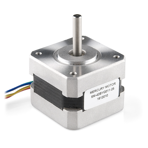 |
| Stepper Motor (200rpm) |
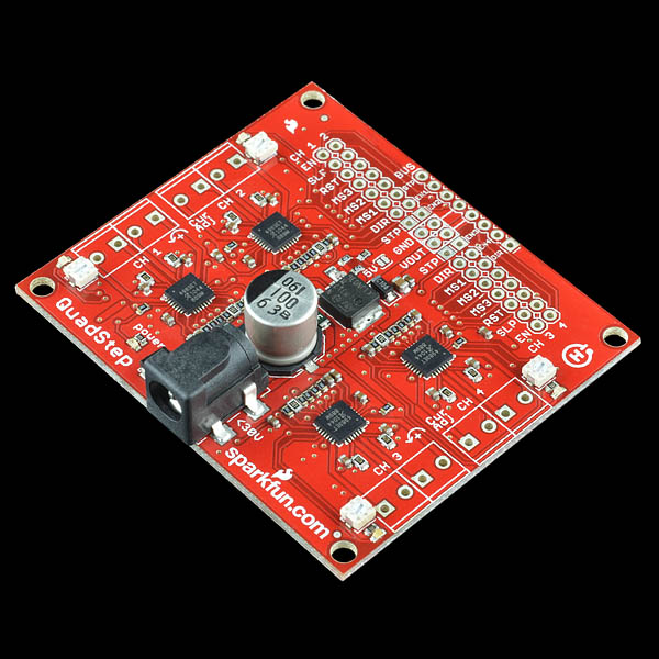 |
| Quad-Stepper Motor Controller |
Sensors
As a proof of concept for future projects, I decided to sense the position of robot's linkages with accelerometers and gyroscopes. Unfortunately, purchasing 3 inertial measurement units (IMU) was not in my budget for this project but I should be able to achieve similar results with accelerometers, gyroscopes, and a Kalman filter... since those are the components of an IMU! I purchased three accelerometers and 3 gyroscopes from Adafruit Industries (https://www.adafruit.com/); which has outstanding tutorials and cool projects for all levels. Sparkfun also has various accelerometers, gyros, and IMUs that would work equally as well. The pages for each of the sensors from Adafruit has soldering, connections to the Arduino, and Arduino sketches and libraries for each sensor so you can get up and running quickly.
Here's the accelerometer (https://www.adafruit.com/products/1231)
 w/ I2C/SPI - Click Image to Close") |
| ADXL345 Triple Axis Accelerometer |
 Triple-Axis Gyro Breakout Board - Click Image to Close") |
| L3GD20 Triple Axis Gyroscope |

No comments:
Post a Comment